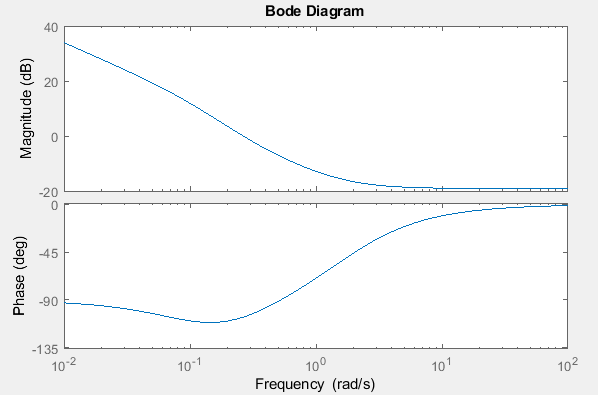
This function tells you how the device modifies signals with different frequencies. This behavior can be summarized using an important function called a transfer function. The output signal will also acquire a phase difference with respect to the input signal, and this phase difference will be a function of frequency. In the presence of weak damping, the output signal reaches a maximum amplitude at resonance. This circuit acts as a bandpass filter that strongly attenuates signals with frequencies that are far from resonance. Take, for example, an RLC circuit with all elements in series. When designing an electronic filter or amplifier, the output amplitude and phase of the output signal will depend on the frequency of the input signal. When examining the behavior of a filter or amplifier, you’ll need to calculate how signals with different frequencies are attenuated or amplified as they are sent through the device. What is a Bode Plot?Ī Bode plot is a specific type of plot that is used to understand and summarize how an electronic circuit (specifically, a linear time-invariant circuit) affects AC signals with different frequencies. Understanding Bode plots helps you optimize your design for specific applications. This simple mathematical tool is vital for understanding the behavior of filters, amplifiers, control systems, oscillators, and other electronic devices. Instead, I get to learn more about amplifiers using Bode plots.

I had plenty of fun experimenting with the settings on the amplifier and listening to the sound change, all while annoying my parents in the process. Picture the scene: a 10 year old child just received their first Fender electric guitar with matching amplifier for their birthday and proceeds to crank away.


 0 kommentar(er)
